Choosing the right Voltage Transformers begins with understanding the measurement task, not simply comparing catalog prices. These devices reduce high system voltages to safe, standardized levels for meters, relays, and control equipment. A poor selection can distort readings, overheat windings, or delay protective action during a fault.
Power-engineering author John J. Winders Jr. states, “A transformer is only as good as the system in which it operates.” That principle deserves attention. Engineers should examine primary voltage, secondary voltage, frequency, burden, accuracy class, insulation level, and installation environment. A 13.8 kV substation may require different insulation and accuracy performance than a compact industrial panel. Small details matter.
Check the burden carefully.
Cable length matters too.
Long secondary wiring can increase the connected burden and reduce measurement accuracy. Indoor dry locations may permit a different enclosure than coastal substations exposed to salt and condensation. Protection applications often need dependable performance during abnormal current conditions, while metering applications may prioritize precise readings near normal load.
Experience also shows that specifications are not always complete. I have seen projects focus on ratio accuracy while overlooking grounding, terminal access, and future circuit expansion. That is an avoidable weakness. The best choice combines manufacturer documentation, applicable technical standards, verified test data, and advice from a qualified power engineer. No single model fits every network. Careful selection creates cleaner measurements, safer maintenance, and more dependable protection throughout the equipment’s service life.
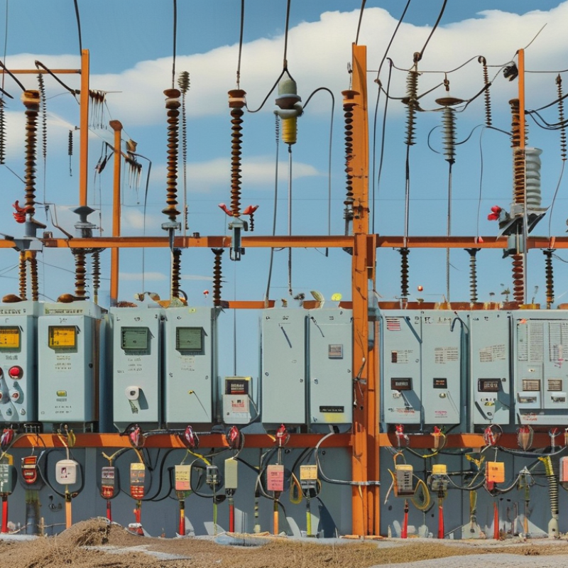
IEC 61869-3 and IEEE C57.13 should guide the selection of inductive voltage transformers. IEC 61869-3 covers requirements for inductive voltage transformers used in measurement and protection. IEEE C57.13 provides North American requirements for instrument transformers, including accuracy, insulation, and testing. These standards overlap, but they are not interchangeable.
For revenue metering, select a transformer with a suitable measurement accuracy class and rated burden. Protection applications need stable performance during faults, not only precise readings during normal load. Check ratio error, phase displacement, insulation level, frequency, and thermal limits. Indoor units may use cast insulation, while outdoor substations often require weather-resistant housings and longer creepage distances.
Do not treat capacitive voltage transformers as identical to inductive units. IEC 61869-3 addresses inductive designs, while capacitive voltage transformers fall under a separate IEC standard. IEEE C57.13 also uses classifications and test practices that may differ from IEC terminology. Mixing clauses can create hidden compliance gaps.
Grid expansion increases this risk. The IEA Electricity 2024 report forecasts global electricity demand growth of about 4% annually through 2026. The U.S. Department of Energy’s National Transmission Needs Study indicates that transmission capacity may need to grow 60% by 2030. In practice, engineers should verify the complete system specification, not rely on a familiar catalog description. A small mistake in burden selection can distort protection signals. That part deserves more attention.
: Measure the actual network voltage at the installation point. Check phase connections and distinguish line-to-line from line-to-ground voltage. Do not trust the panel label alone. Measure it.
Match the transformer exactly to the relay, meter, or control device. A 100 V input may give inaccurate readings with a 110 V transformer. The difference looks small, but the result may not be harmless. Not quite interchangeable.
Check frequency, accuracy class, rated burden, insulation level, and voltage ratio together. A correct ratio cannot compensate for excessive cable burden or poor insulation selection. Review terminal markings and test certificates before installation.
Add the burdens of meters, relays, fuses, and secondary wiring. Include cable losses using current squared multiplied by resistance. Allow practical margin, but avoid excessive oversizing. More VA is not always better.
Long cables create additional resistance and consume part of the transformer’s burden capacity. This can increase ratio error and phase error. A small control cabinet may hide a surprisingly long cable route.
Consider system voltage, altitude, pollution, moisture, and transient exposure. Select power-frequency and lightning-impulse withstand levels from the site insulation study. A value suitable for one network may fail in another. The figure is not universal.
Verify both thermal withstand current and dynamic peak withstand current. Compare them with the switchgear fault study, including asymmetrical fault peaks. Also inspect conductor bracing, mounting strength, and secondary protection.
Choose based on temperature, humidity, dust, salt, sunlight, ventilation, and maintenance access. Indoor units suit controlled rooms, while outdoor units need stronger weather protection. Oil designs require containment and leak monitoring. Cast-resin units avoid liquid leakage, but poor ventilation still causes overheating.
Record ambient temperature, humidity, pollution, vibration, clearance, cable access, and cleaning restrictions. Check future load growth before selecting the smallest suitable unit. A transformer may fit the drawing but fail the room. That lesson can be expensive.
Choosing the right Voltage Transformers requires careful consideration of both technical requirements and installation conditions. Start by identifying the suitable transformer type according to IEC 61869-3 or IEEE C57.13, then match the primary and secondary voltage ratings with the power system and common 100 V or 110 V secondary standards. The selected accuracy class should reflect the application: classes 0.1, 0.2, and 0.5 are generally suited to measurement, while protection applications may require a 3P class.
Before final selection, verify the rated burden in VA to ensure reliable operation with connected meters, relays, and instruments. Insulation level and short-circuit withstand capability must also meet the system’s safety and performance requirements. Finally, evaluate the installation environment. Indoor, outdoor, oil-insulated, and cast-resin designs offer different advantages depending on space, weather exposure, fire considerations, maintenance needs, and operating conditions. A balanced review of these factors helps ensure accurate measurement, dependable protection, and long-term service stability.

 Igoye Energy