ODM GNM1 Plastic Enclosure Circuit Breaker Manufacturer, Factories

GNM1 series plastic case circuit breakers (hereinafter referred to as circuit breakers) are new circuit breakers developed by our company using international level design and manufacturing technology. The circuit breakers have overload, short circuit and under voltage protection functions, and can protect the lines and power equipment from damage. This series of circuit breakers has the characteristics of compact structure, small size, high breaking speed, short arcing, and complete internal and external accessories.

Product Description

Purpose and scope of use

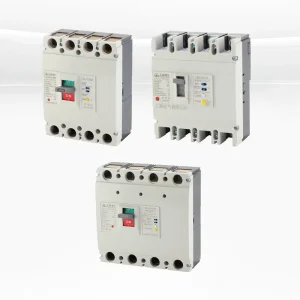
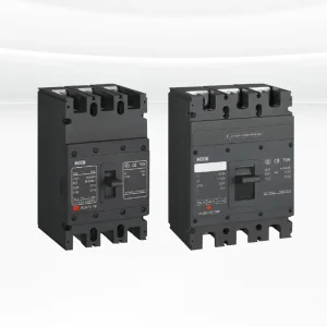
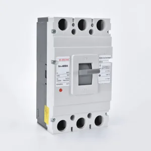
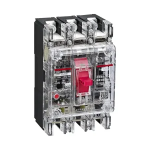
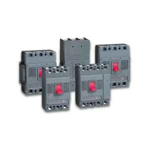
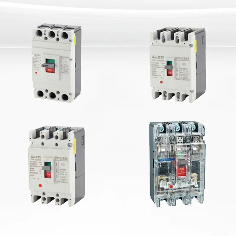
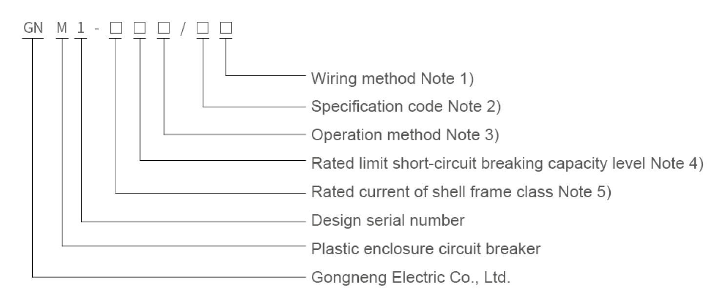
GNM1 series molded case circuit breakers have a rated insulation voltage of 800V, are suitable for AC 50Hz, rated working voltage 690V and below, and rated working current from 10A to 1250A for infrequent switching and infrequent motor starting (GNM1-800 and GNM1-1250 have no motor protection).

Standards IEC60947-1 and GB/T14048.1 Low-voltage switchgear and control equipment General provisions
IEC60947-2 and GB/T14048.2 Low-voltage switchgear and control equipment Low-voltage circuit breakers
IEC60947-4 and GB/T14048.4 Electromechanical circuit breakers and motor starters
IEC60947-5-1 and GB/T14048.5 Electromechanical control circuit electrical appliances

Normal working conditions

  • The altitude of the installation site shall not exceed 2000m;
  • The ambient air temperature is -5°C~+40°C, and the average value of 24 hours does not exceed +35°C;
  • The relative air humidity of the installation site shall not exceed 50% at the maximum temperature of +40°C, and the average minimum temperature of the wettest month shall not exceed +25°C, and the average maximum relative humidity of the month shall not exceed 90%, and the condensation on the surface of the product due to temperature changes shall be considered;
  • The pollution level is level 3;
  • The safety category of the main circuit breaker and the undervoltage tripper is Ⅲ, and the installation category of the other auxiliary circuits and control circuits is II;
  • Able to withstand the influence of humid air, salt spray, oil pollution, mold and nuclear industrial environment;
  • Installed in a place where there is no explosion hazard and no conductive dust, no enough to corrode metal and damage insulation;
  • There is no rain and snow at the installation site;
  • The circuit breaker has an isolation function, and the symbol is _/| \/ .

Model meaning

Model Meaning Diagram 01
Note 1: The wiring method is divided into: board front wiring, board back wiring, plug-in board back wiring, plug-in board front wiring.
Note 2: The specification code consists of six digits.
Model Meaning Diagram 02
Note 3: Operation mode: no code for direct operation of the handle, Z for rotating the handle operation, and P for electric operation.
Note 4: The rated limit short-circuit breaking capacity levels are divided into L type, M type, and H type.
Note 5: The rated current of the shell frame level is divided into 63, 125, 250, 400, 630, 800 and 1250.

Tripping method and attachment code

Tripping method Attachment code
Shunt tripper Auxiliary contacts Under voltage trippers Shunt tripper Auxiliary contacts Shunt tripper Under voltage trippers Two sets of auxiliary contacts Auxiliary contacts Undervoltage trippers
Electromagnetic tripping 210 220 230 240 250 260 270
Duplex trip 310 320 330 340 350 360 370
Tripping method Attachment category
Alarm contacts Shunt tripper Alarm contacts Auxiliary contacts Alarm contacts Undervoltage trippers Alarm contacts Shunt trip alarm Contact Auxiliary Contacts Two sets of auxiliary contacts Alarm contacts Auxiliary contacts, undervoltage trippers, alarm contacts
Electromagnetic tripping 208 218 228 238 348 268 278
Duplex trip 308 318 320 338 348 368 378
Note 1: The first digit 2 of the tripper mode and the internal accessory code represents the electromagnetic (instantaneous) tripper, and 3 represents the thermal-electromagnetic (duplex) tripper. The last two digits represent the internal accessory code; if there is no accessory, it is represented by 00.
Note 2: A pair of auxiliary contacts (i.e., one normally open, one normally closed) in GNM1-400, 630, 800 in 248, 348, 278 and 378 specifications, and one auxiliary contact in 268 and 368 specifications.

Installation method

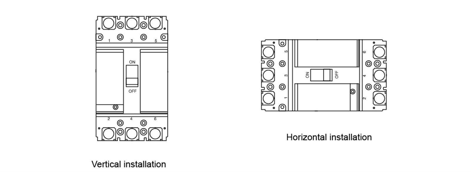
This series of circuit breakers is generally installed vertically (see figure below).

Installation Method Diagram

Frequently Asked Questions

Q: What is the rated insulation voltage of the GNM1 series molded case circuit breakers?
The GNM1 series molded case circuit breakers feature a rated insulation voltage of 800V.
Q: Which GNM1 models do not include motor protection?
The GNM1-800 and GNM1-1250 models do not feature motor protection.
Q: What are the ambient temperature requirements for operating GNM1 circuit breakers?
The ambient air temperature must remain between -5°C and +40°C, and the average temperature over a 24-hour period should not exceed +35°C.
Q: Can the GNM1 series circuit breakers handle humid and salty environments?
Yes, these circuit breakers are built to withstand the influences of humid air, salt spray, oil pollution, mold, and nuclear industrial environments.
Q: What are the available installation wiring methods for this series?
The wiring methods are divided into board front wiring, board back wiring, plug-in board back wiring, and plug-in board front wiring.
Q: How should the GNM1 series circuit breakers be positioned during installation?
This series of circuit breakers is designed to be installed vertically in locations free from rain and snow.

Related Products